DER Integration and Voltage Regulation: Volt-VAR Management in High-Penetration Distribution Systems
Published: June 2026 Technical Level: Advanced Category: Protection Systems
Abstract
Voltage regulation on distribution feeders with high penetration of inverter-based distributed energy resources presents a fundamentally different challenge from voltage regulation on passive load feeders. On a passive feeder, voltage decreases monotonically from the substation to the feeder end under load, and voltage regulation equipment (line voltage regulators, switched capacitor banks, LTC transformers) is designed to maintain voltage within ANSI C84.1 Range A limits along this monotonically decreasing profile. When solar PV or battery storage DER inject power at intermediate and remote feeder points, the voltage profile becomes non-monotonic: voltage may peak at the DER interconnection points during periods of high generation and low load, creating overvoltage conditions that the conventional regulation equipment was not designed to manage. This paper develops the voltage regulation analysis framework for high-penetration DER feeders, the volt-VAR optimization (VVO) methodology that coordinates inverter reactive power capability with conventional regulation equipment, and the IEEE 1547-2018 volt-VAR mode requirements that enable coordinated voltage regulation as a standard DER function.
1. Introduction
Distribution voltage regulation engineering has been practiced for over a century with a clear and stable design basis: the feeder voltage drop under peak load is the design constraint, voltage regulators and capacitor banks are the correction tools, and the monotonic voltage profile from substation to feeder end defines the correction required at each point. The deployment of IEEE 1547-2018-compliant inverter-based DER with volt-VAR control capability creates, for the first time, a technology that can provide voltage correction from thousands of distributed points along the feeder simultaneously, but that technology must be coordinated with the conventional regulation equipment to be beneficial rather than destabilizing.
The fundamental shift is from centralized, scheduled voltage correction (regulator tap position controlled by an LDC relay, capacitor bank switched at fixed time schedules) to distributed, real-time voltage correction (inverter reactive power modulated continuously in response to local voltage measurements). The distributed approach has lower per-unit cost (the reactive power capability is embedded in inverter hardware that is already deployed for its primary generation or storage function, at no additional marginal cost), but it requires a coordination framework to prevent the distributed control actions from conflicting with each other or with the conventional equipment.
2. Voltage Impact of DER Generation
2.1 Non-Monotonic Voltage Profiles
The steady-state voltage at any point on a radial distribution feeder is governed by the Kirchhoff voltage law relationship between the sending-end voltage, the line impedance, and the net power flow (load minus generation) at each downstream bus. For a feeder with DER injection at an intermediate bus, the voltage profile from the substation to the feeder end has three segments: a decreasing segment from the substation to the DER bus (where load-driven voltage drop dominates), a voltage step or rise at the DER bus (where DER injection partially or fully offsets the voltage drop), and a decreasing or increasing segment from the DER bus to the feeder end depending on whether the remaining feeder load exceeds or is less than the DER generation.
When solar PV generation at the DER bus exceeds the local load (a condition that occurs regularly in residential areas with high rooftop PV density during midday on weekends and spring days), the power flow from the DER bus toward the substation is positive (the feeder is exporting generation to the substation). In this condition, the voltage at the DER bus can rise above the substation voltage if the line resistance is high, because the line voltage drop direction reverses: the feeder is now a power source rather than a load, and the voltage at the source end (DER bus) is higher than the voltage at the sink end (substation bus). ANSI C84.1 Range A limits voltage to ±5 percent of nominal; a DER bus voltage of 1.06 per unit (6 percent above nominal) is outside the allowable range and requires corrective action.
2.2 Overvoltage Threshold Analysis
The DER penetration level at which overvoltage first becomes a concern (the voltage hosting capacity for overvoltage) depends on the feeder's R/X ratio, the source impedance at the DER bus, and the minimum load that coincides with maximum DER generation. The overvoltage threshold for a DER bus with total DER injection is reached when:
Where: is the substation voltage in per-unit.
and are the line resistance and reactance from substation to DER bus.
and are the minimum feeder load in per-unit (minimum load coincident with maximum DER generation).
As a worked example, take a typical urban distribution feeder with pu and pu (on a 10 MVA base), a substation voltage pu, and a minimum coincident load of pu. For a DER injection of pu at unity power factor ():
which is within the ANSI C84.1 Range A limit. Increasing the injection to pu:
which marginally exceeds the 1.05 pu limit. Interpolating between these two cases, the overvoltage threshold (the voltage hosting capacity at unity power factor) is reached at approximately 0.75 pu DER injection for this feeder. The example illustrates the central role of the line resistance: because the resistance term dominates at unity power factor, a higher-resistance feeder reaches its hosting limit at a lower DER penetration, and absorbing reactive power (negative ) through Volt-VAR control is the lever that pushes the threshold higher.
The non-monotonic voltage rise that DER produces is illustrated in Figure 1, which plots the voltage profile along the feeder with and without distributed generation.
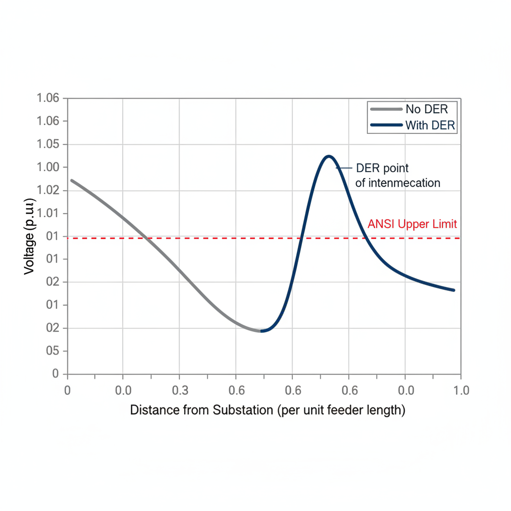
Figure 1. Feeder voltage profile with and without DER. The horizontal axis is distance from the substation in per unit of feeder length and the vertical axis is voltage in per unit. Without DER the voltage declines monotonically toward the feeder end; with DER it rises to a hump at the point of interconnection that can exceed the ANSI upper limit. The engineer should observe that the conventional assumption of monotonically declining voltage, on which line-drop-compensating regulators are set, no longer holds, which is why DER interconnection requires explicit overvoltage analysis at the point of common coupling.
3. Volt-VAR Optimization
3.1 IEEE 1547-2018 Volt-VAR Mode
IEEE 1547-2018 Section 6.4.2 defines the Volt-VAR function as a required capability for all Category II and Category III DER (with some exceptions based on size and voltage level). The Volt-VAR function varies the DER inverter's reactive power output as a function of the local terminal voltage, following a piecewise-linear characteristic specified by the distribution operator:
The characteristic is defined by four voltage setpoints ( through ) and four reactive power limits ( at , 0 at , 0 at , at ). When the terminal voltage is between and (the deadband), the inverter operates at unity power factor. When the voltage rises above , the inverter absorbs reactive power (capacitive load) to counteract the voltage rise. When the voltage falls below , the inverter injects reactive power (capacitive source) to support the voltage. The slope of the characteristic in the regions between and and between and determines the reactive power response per unit of voltage deviation.
The maximum reactive power available for Volt-VAR control depends on the inverter's apparent power rating and its current active power output. The reactive power capability at active power output is:
Where is the inverter's apparent power rating in kVA. For an inverter operating at 80 percent of its active power rating, the maximum reactive power capability is pu of rated apparent power, substantial reactive power support available even under high-generation conditions.
3.2 Coordination with Conventional Regulation Equipment
The most common coordination failure in high-penetration DER feeders is hunting between the inverter Volt-VAR controls and the line voltage regulator. When the inverter's reactive power absorption reduces the feeder voltage at the regulator's voltage sensing point, the regulator's LDC relay may interpret the lower measured voltage as an inadequate response and raise the tap position, which increases the substation voltage, which increases the voltage at the DER bus, which causes the inverter to absorb more reactive power, which reduces the regulator sensing voltage again. The cycle can continue indefinitely, causing the regulator to hunt through its full tap range while the inverters continuously absorb and release reactive power.
The solution to this coordination problem is to set the deadband of the DER Volt-VAR characteristic ( to ) wider than the voltage range within which the voltage regulator would normally operate without taking a tap step. If the regulator's bandwidth (the dead band before a tap change is initiated) is ±1.5 V on a 120 V base (±1.25 percent), the DER Volt-VAR deadband should be set to at least ±2 percent to ensure that the DER does not respond to voltages within the regulator's normal operating range.
Related Work
The analysis in this paper connects to several companion studies in this library. Readers concerned with the upstream and downstream engineering will find DER Integration Grid Impact Analysis develops a closely related aspect of the same problem, while DER Integration and Distribution System Protection extends the treatment into an adjacent domain. For the broader methodological context, Distribution Planning for High DER Penetration provides complementary depth.
Conclusion
Voltage regulation on high-penetration DER feeders differs fundamentally from regulation on passive feeders because DER injection makes the voltage profile non-monotonic, so that voltage may peak at an intermediate or remote interconnection point rather than declining steadily from the substation, and the analysis developed in this paper shows that conventional regulation equipment designed for a monotonic profile can be actively counterproductive under this condition. The central engineering conclusion is that the IEEE 1547-2018 volt-VAR mode of the DER inverters must be coordinated with the existing line regulators, capacitor banks, and LTC transformers rather than operated independently, because uncoordinated volt-VAR response can hunt against the conventional equipment and cause excessive tap operations. For the practicing engineer, the operative discipline is to analyze the overvoltage threshold at the minimum-load, maximum-generation condition, which is the binding case for DER-driven voltage rise, and to design the volt-VAR settings and the coordination with conventional regulation as an integrated control problem rather than as a sequence of independent device settings.
References
[1] IEEE Standard 1547-2018, Standard for Interconnection and Interoperability of Distributed Energy Resources, IEEE, 2018.
[2] ANSI C84.1-2020, Electric Power Systems and Equipment: Voltage Ratings (60 Hz), ANSI, 2020.
[3] EPRI, Advanced Inverter Functions for Distributed Energy Resources, EPRI Technical Report 3002007376, 2016.
[4] EPRI, Hosting Capacity Analysis for Distributed Energy Resources, EPRI 3002004588, 2022.
[5] H. Turitsyn, P. Sulc, S. Backhaus, and M. Chertkov, "Options for Control of Reactive Power by Distributed Photovoltaic Generators," Proceedings of the IEEE, vol. 99, no. 6, 2011.
[6] K. P. Schneider et al., "Evaluating the Metrics of Volt-VAR Optimization," IEEE PES General Meeting, 2013.
[7] IEEE Standard C57.15-2017, Standard Requirements, Terminology, and Test Code for Step-Voltage Regulators, IEEE, 2017.
[8] NERC, Reliability Guideline: Distributed Energy Resources Connection Modeling, NERC, 2022.