Short-Circuit Analysis: ANSI/IEEE Calculation Methods and Equipment Duty Evaluation
Published: June 2026
Technical Level: Advanced
Category: Power System Analysis
Abstract
Short-circuit analysis establishes the maximum fault currents a power system can deliver and is the foundation upon which equipment interrupting ratings, bus bracing, protective device coordination, and arc flash incident energy are all determined. This paper develops the ANSI/IEEE methodology for fault current calculation, beginning with the per-unit representation of the system and the symmetrical-component framework that resolves unbalanced faults into decoupled positive-, negative-, and zero-sequence networks. The four canonical fault types (three-phase, single-line-to-ground, line-to-line, and double-line-to-ground) are expressed in terms of their sequence-network connections, and the dominance of the three-phase and single-line-to-ground cases in equipment rating is explained. The paper then addresses the role of the X/R ratio in determining the decaying DC offset that drives asymmetrical interrupting duty, develops the equipment duty comparison that an interrupting device must satisfy under ANSI C37, and examines the distinct fault-current contributions of synchronous and inverter-based distributed generation, which differ by nearly an order of magnitude and which materially change the fault duty and protection coordination of a modern distribution system.
1. Introduction
Every protective device, every bus, and every conductor in a power system must be rated to withstand or to interrupt the largest fault current that can flow at its location. A short-circuit fault, the unintended connection of energized conductors to one another or to ground, collapses the circuit impedance to the small value of the system source impedance, allowing a current many times the load current to flow until a protective device clears it. The magnitude of that current determines whether a circuit breaker will interrupt the fault safely or fail catastrophically, whether a busbar will remain in place or be deformed by the magnetic forces between conductors, and how much thermal energy is released into an arc flash. Short-circuit analysis is therefore not an optional refinement but a code-mandated prerequisite: the National Electrical Code requires in Article 110.9 that equipment intended to interrupt fault current have an interrupting rating sufficient for the available current, and in Article 110.10 that the circuit components be selected and coordinated to withstand the fault until it is cleared.
The analysis serves four distinct engineering purposes that share a common calculation but apply its results differently. For equipment duty evaluation, the engineer compares the calculated fault current against the interrupting and withstand ratings of breakers, fuses, and buswork. For protection coordination, the fault currents at successive points in the system establish the operating points on the time-current curves that must be coordinated for selectivity. For arc flash analysis, the bolted fault current and the protective device clearing time at that current together determine the incident energy. And for system planning, the evolution of fault levels as load grows and generation is added governs when equipment must be upgraded. The methodology developed in this paper is that of the ANSI/IEEE C37 standards, which are the controlling documents for short-circuit calculation and equipment application in North American practice.
2. The Per-Unit System and Symmetrical Components
2.1 Per-Unit Representation
Short-circuit calculations are performed in the per-unit system, in which every quantity is expressed as a fraction of a chosen base value. The per-unit system removes the transformer turns ratios from the calculation (a per-unit impedance referred to one side of a transformer is identical on the other side when a consistent base is used) and allows impedances at different voltage levels to be combined directly. The base impedance at a given voltage level is established from the chosen base power and base voltage:
Where:
is the base impedance in ohms.
is the base line-to-line voltage in volts.
is the base three-phase apparent power in volt-amperes.
Equipment impedances supplied on equipment nameplates as percentages on the equipment's own rating are converted to the common system base before the network is reduced, and the source impedance representing the utility supply is derived from the utility-supplied available fault duty at the service point.
2.2 The Symmetrical-Component Transformation
A balanced three-phase fault preserves the symmetry of the system and can be solved on a single-phase positive-sequence basis. The three unbalanced fault types do not, and their solution requires the method of symmetrical components, which resolves any set of three unbalanced phasors into three balanced sets: a positive-sequence set with normal phase rotation, a negative-sequence set with reversed rotation, and a zero-sequence set in which all three phasors are identical and in phase. The power of the transformation is that, for a system with no rotating-machine saliency, the three sequence networks are mutually decoupled, so each can be reduced independently to a single Thévenin impedance (, , and ) as seen from the fault point. The unbalanced fault is then solved by connecting these three sequence networks in the particular configuration dictated by the fault type.
3. Fault Types and Their Calculation
3.1 The Three-Phase Fault
The three-phase bolted fault shorts all three phases together symmetrically. It produces the highest fault current in the majority of systems and is the case used for equipment interrupting and withstand duty evaluation. Because the fault is balanced, only the positive-sequence network participates, and the fault current is simply the pre-fault voltage divided by the positive-sequence Thévenin impedance to the fault:
Where:
is the symmetrical three-phase fault current in per unit.
is the pre-fault voltage at the fault point, customarily taken as 1.0 per unit.
is the positive-sequence Thévenin impedance from the source to the fault in per unit.
3.2 The Single-Line-to-Ground Fault
The single-line-to-ground fault, in which one phase contacts ground, is by a wide margin the most common fault type, accounting for the majority of all faults on overhead and underground systems. Its solution requires the series connection of all three sequence networks, because the fault couples the positive-, negative-, and zero-sequence circuits:
Where:
is the single-line-to-ground fault current in the faulted phase in per unit.
is the pre-fault voltage at the fault point in per unit.
, , are the positive-, negative-, and zero-sequence Thévenin impedances to the fault in per unit.
On systems with a solidly grounded source close to the fault, the zero-sequence impedance can be smaller than the positive-sequence impedance, and the single-line-to-ground fault current can then exceed the three-phase fault current. This condition must be checked explicitly, because the equipment ground-fault duty rather than the three-phase duty governs the rating in such cases.
3.3 The Line-to-Line and Double-Line-to-Ground Faults
The line-to-line fault, a short between two phases without ground involvement, connects the positive- and negative-sequence networks in opposition and produces a current related to the three-phase value by the negative-sequence impedance:
Where:
is the line-to-line fault current in per unit.
, are the positive- and negative-sequence Thévenin impedances to the fault in per unit.
Because the negative-sequence impedance is close to the positive-sequence impedance in most systems, the line-to-line fault current is approximately 87 percent of the three-phase value and is rarely the governing case for equipment rating. The double-line-to-ground fault, in which two phases contact ground simultaneously, requires the parallel connection of the negative- and zero-sequence networks with the positive-sequence network and is solved by the full sequence-network analysis; it is the least common fault type and seldom governs equipment duty, but it is evaluated where ground-fault protection settings depend on the complete fault spectrum.
4. Asymmetry and the X/R Ratio
The fault-current expressions above give the symmetrical alternating-current magnitude, but the instantaneous current at the moment of fault inception contains an additional decaying direct-current component. This DC offset arises because the current in an inductive circuit cannot change instantaneously; its initial magnitude depends on the point on the voltage wave at which the fault occurs, and its rate of decay is governed by the ratio of the system reactance to its resistance at the fault point. A high X/R ratio means a slowly decaying offset and therefore a larger total asymmetrical current during the early cycles of the fault, which is precisely the interval in which a circuit breaker must interrupt.
The asymmetrical current that a breaker must interrupt is obtained by multiplying the symmetrical current by an asymmetry factor that depends on the X/R ratio and the breaker's contact-parting time. The decaying DC component follows an exponential governed by the system time constant:
Where:
is the instantaneous DC offset current at time after fault inception in amperes.
is the symmetrical root-mean-square fault current in amperes.
is the DC decay time constant in seconds.
is the ratio of system reactance to resistance at the fault point.
is the system frequency in hertz.
The practical consequence is that the X/R ratio must be calculated and applied correctly, because a breaker rated adequately for the symmetrical current can be misapplied if the asymmetrical duty implied by a high X/R ratio exceeds its tested interrupting capability. ANSI C37.010 provides the multiplying factors that translate the symmetrical calculated current into the asymmetrical duty a breaker must meet, as a function of the X/R ratio and the breaker's rated interrupting time.
5. Equipment Duty Evaluation
The purpose of the calculation is ultimately a comparison: the fault duty imposed at each device location must not exceed the device's rating. For an interrupting device, the governing condition is that the device's interrupting rating equal or exceed the asymmetrical fault current it will be required to interrupt:
Where:
is the device's rated interrupting current in amperes.
is the calculated symmetrical fault current at the device in amperes.
is the asymmetry multiplying factor from ANSI C37.010 for the applicable X/R ratio and contact-parting time.
A parallel comparison applies to the momentary or close-and-latch duty, which is evaluated against the first-cycle asymmetrical current, and to the thermal and mechanical withstand of buswork, which must survive the fault current for the full clearing time. Equipment duty violations are most frequently discovered in older facilities where load and source growth have raised the available fault current above the interrupting ratings of breakers selected decades earlier; a short-circuit study performed when a service is upgraded or when significant generation is added is the mechanism by which such latent violations are identified before they manifest as a breaker failure.
6. Fault Contribution from Distributed Generation
The growth of distributed energy resources has changed the short-circuit landscape, because the two principal classes of distributed generation contribute fault current in fundamentally different ways. A synchronous generator interconnected to the distribution system behaves like any other rotating machine during a fault: it delivers a substantial sub-transient fault current, commonly in the range of five to eight times its rated current, decaying through the transient to the synchronous period. Synchronous distributed generation therefore adds materially to the fault duty of nearby equipment and must be modeled with its sub-transient reactance in the positive-sequence network.
Inverter-based generation behaves entirely differently. The power-electronic converter that interfaces a photovoltaic array or a battery to the grid actively limits its output current to protect its semiconductor switches, so its fault contribution is restricted by control action to approximately 1.0 to 1.2 times its rated current, a small fraction of what a synchronous machine of the same rating would deliver. This current-limited behavior means that inverter-based resources contribute little to the peak fault duty that governs equipment ratings, but it creates a distinct and more difficult problem for protection: the modest and short-lived fault contribution of inverters may be insufficient to operate overcurrent protection reliably, particularly when the system is islanded from the utility source and the inverters are the only generation present. The fault-current difference between the two classes is large enough that a distribution system's protection philosophy must account explicitly for which type of generation is present, and the short-circuit study must model the inverter sources with their control-limited current characteristic rather than with a conventional impedance.
7. Worked Example: Three-Phase and Line-to-Ground Fault on a 480 V Bus
Consider a 480 V bus fed from a 1000 kVA, 13.8 kV to 480 V transformer with a nameplate impedance of 5.75 percent and an X/R ratio of 6.5, supplied from a 13.8 kV utility source whose available three-phase fault duty is 500 MVA. The objective is to calculate the three-phase and single-line-to-ground fault currents at the 480 V bus, apply the X/R correction, and compare the result against the duty of a candidate molded-case circuit breaker.
The calculation is carried out in per unit on a 1000 kVA base with a 480 V base voltage, for which the base current is:
Where:
is the chosen apparent-power base in VA.
is the line-to-line base voltage in V.
The utility source impedance referred to the chosen base is the base apparent power divided by the source fault duty:
Where:
is the utility three-phase fault duty in MVA.
The transformer impedance is already expressed on a 1000 kVA base as 0.0575 per unit. The total positive-sequence impedance to the fault is the series sum of the source and transformer impedances:
The symmetrical three-phase fault current is the base current divided by the total per-unit impedance:
For the single-line-to-ground fault, the positive-, negative-, and zero-sequence networks combine in series. Taking the negative-sequence impedance equal to the positive-sequence impedance and the transformer zero-sequence impedance approximately equal to its positive-sequence value for a delta-wye transformer with a solidly grounded secondary neutral, the line-to-ground fault current is:
Where:
is the total negative-sequence impedance to the fault in per unit.
is the total zero-sequence impedance to the fault in per unit.
For this delta-wye transformer the line-to-ground fault current is essentially equal to the three-phase value, a characteristic outcome when the zero-sequence impedance is comparable to the positive-sequence impedance; on systems where the zero-sequence path is higher in impedance the line-to-ground current would be correspondingly lower. The symmetrical fault current must now be adjusted for the asymmetry that the X/R ratio produces. For an X/R of 6.5 the asymmetrical peak and the rms asymmetrical current exceed the symmetrical value; the multiplying factor applied to the symmetrical rms current for the first-cycle duty, taken from the ANSI/IEEE C37 multiplying-factor curves at this X/R, is approximately 1.04 for the rms asymmetrical current, giving:
A molded-case circuit breaker applied at this bus must therefore have an interrupting rating of at least 21.0 kA rms symmetrical at 480 V, and standard practice selects the next standard rating above the calculated duty (a 25 kA or, more conservatively, a 35 kA interrupting rating) to preserve margin against future source strengthening. The example illustrates the full chain of the calculation: the per-unit reduction of source and transformer impedance, the series combination of sequence networks for the unbalanced fault, and the X/R correction that converts the symmetrical result into the asymmetrical duty against which equipment is rated.
The result chain is summarized in the duty-evaluation table below, which is the form in which a short-circuit study presents its conclusion for each bus:
| Quantity | Value | Basis |
|---|---|---|
| Base current (1000 kVA, 480 V) | 1,203 A | |
| Total positive-sequence impedance | 0.0595 pu | Source 0.002 + transformer 0.0575 |
| Symmetrical three-phase fault | 20.2 kA | |
| Single-line-to-ground fault | 20.4 kA | Series sequence networks |
| X/R ratio at fault | 6.5 | Source plus transformer |
| Asymmetry multiplying factor | 1.04 | ANSI C37.010, first-cycle |
| Asymmetrical interrupting duty | 21.0 kA | |
| Selected breaker rating | 25–35 kA | Next standard rating with margin |
The asymmetry that the multiplying factor accounts for is shown in Figure 1, which decomposes the fault current into its alternating and direct-current components over the first three cycles.
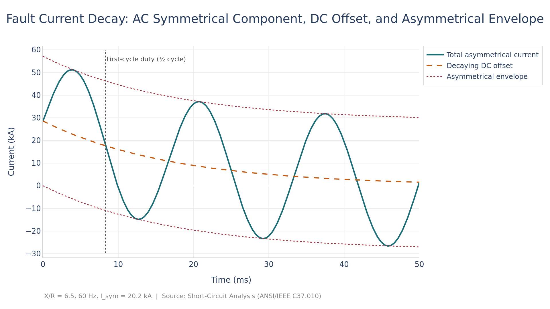
Figure 1. Fault current decay for the worked example (X/R = 6.5, I_sym = 20.2 kA), showing the AC symmetrical component, the decaying DC offset, and the asymmetrical envelope, with the first-cycle interrupting-duty instant marked.
The figure shows why the asymmetrical duty exceeds the symmetrical value: in the first half cycle the decaying DC offset adds to the AC peak, producing a total current well above the symmetrical envelope, and it is this elevated current that a breaker must interrupt during its contact-parting interval. The reader should observe that the DC offset decays toward zero within a few cycles, so the multiplying factor is largest for fast breakers that part their contacts early and approaches unity for slower devices, which is precisely the dependence on contact-parting time that the ANSI C37.010 multiplying-factor curves tabulate.
8. Conclusion
Short-circuit analysis underlies the safe application of every interrupting device and current-carrying component in a power system. The calculation proceeds in the per-unit system and resolves unbalanced faults through symmetrical components, reducing each fault type to a defined connection of the positive-, negative-, and zero-sequence networks. The three-phase fault generally governs equipment interrupting duty, while the single-line-to-ground fault is both the most common and, on solidly grounded systems, occasionally the most severe. The X/R ratio determines the decaying DC offset that sets the asymmetrical interrupting duty, and its correct evaluation is essential to avoid breaker misapplication. The duty comparison against ANSI C37 ratings is the engineering deliverable of the study, and the increasing presence of distributed generation (synchronous machines contributing several times their rated current and inverters limited to near their rated current) requires that the modern study represent each source by its true fault behavior, both to size equipment correctly and to ensure that protection remains reliable across grid-connected and islanded operating states.
Related Work
The analysis in this paper connects to several companion studies in this library. Readers concerned with the upstream and downstream engineering will find Short-Circuit Analysis develops a closely related aspect of the same problem, while Arc Flash Risk Assessment extends the treatment into an adjacent domain. For the broader methodological context, Protection Coordination Study provides complementary depth.
References
[1] IEEE Standard C37.010-2016, IEEE Application Guide for AC High-Voltage Circuit Breakers Rated on a Symmetrical Current Basis, IEEE, 2016.
[2] IEEE Standard C37.13-2015, IEEE Standard for Low-Voltage AC Power Circuit Breakers Used in Enclosures, IEEE, 2015.
[3] IEEE Standard 551-2006, IEEE Recommended Practice for Calculating Short-Circuit Currents in Industrial and Commercial Power Systems (Violet Book), IEEE, 2006.
[4] IEEE Standard 141-1993, IEEE Recommended Practice for Electric Power Distribution for Industrial Plants (Red Book), IEEE, 1993.
[5] NFPA 70-2023, National Electrical Code, National Fire Protection Association, 2023.
[6] IEEE Standard 1547-2018, IEEE Standard for Interconnection and Interoperability of Distributed Energy Resources with Associated Electric Power Systems Interfaces, IEEE, 2018.
[7] J. L. Blackburn and T. J. Domin, Protective Relaying: Principles and Applications, 4th ed., CRC Press, 2014.
[8] P. M. Anderson, Analysis of Faulted Power Systems, IEEE Press, 1995.
[9] J. C. Das, Power System Analysis: Short-Circuit Load Flow and Harmonics, 2nd ed., CRC Press, 2011.
[10] IEEE Standard 1584-2018, IEEE Guide for Performing Arc-Flash Hazard Calculations, IEEE, 2018.