Short-Circuit Thermal Withstand of Insulated Conductors: Adiabatic and Non-Adiabatic Analysis to IEC 60949
Published: August 2026 Technical Level: Advanced Category: Power Systems Design
Abstract
During a short circuit, an insulated cable must carry a fault current many times its continuous rating for the brief interval before an upstream protective device clears the fault, and the conductor temperature rise over that interval must remain within a limit set by the thermal endurance of the insulation. The governing design question is therefore not how much current a conductor can carry indefinitely, but how much energy it can absorb in a fraction of a second without the insulation exceeding its permitted short-circuit temperature. This paper develops the thermal withstand analysis of insulated conductors from first principles, beginning with the adiabatic energy balance that underlies the familiar sizing rule, deriving the rating constant directly from the temperature-dependent resistivity and volumetric heat capacity of the conductor material, and then extending the analysis to the non-adiabatic correction of IEC 60949 that accounts for heat conducted into the surrounding insulation and bedding during longer faults. A worked example for a 240 mm² copper XLPE cable establishes the permissible short-circuit currents across the practical range of clearing times, and a comparison of the adiabatic and non-adiabatic results quantifies the conservatism of the simple sizing rule. The paper closes with practical guidance on selecting the correct clearing time, reconciling the withstand current against the protective device let-through energy, and applying the method consistently across copper and aluminium conductors with XLPE and PVC insulation.
1. The Thermal Withstand Problem
1.1 Why Short-Circuit Rating Differs from Continuous Ampacity
The continuous ampacity of an insulated conductor is a steady-state quantity: it is the current at which the heat generated by resistive losses in the conductor exactly balances the heat dissipated to the surroundings, holding the conductor at its permitted continuous operating temperature. That balance is a thermal equilibrium reached over minutes to hours, and it is governed by the thermal resistance of the insulation, the installation method, and the ambient conditions. Short-circuit rating is a fundamentally different problem. A fault current of tens of kiloamperes flows for only a few tenths of a second to a few seconds before the protective device operates, and over that brief interval there is no time for the heat generated in the conductor to escape into the surroundings. The conductor heats almost entirely by storing the dissipated energy in its own thermal mass.
This distinction matters because it changes which material properties govern the design. Continuous ampacity depends on the thermal resistivity of the insulation and the geometry of heat removal; short-circuit withstand depends instead on the resistivity and the volumetric heat capacity of the conductor metal itself, together with the maximum temperature the insulation can briefly tolerate. For cross-linked polyethylene (XLPE) insulation the continuous conductor temperature limit is 90 °C, while the short-circuit limit is 250 °C; the insulation can survive that much higher temperature precisely because the excursion lasts only a fraction of a second and does not accumulate over the cable life. The engineer's task is to confirm that, for the credible fault current and the actual protective clearing time, the conductor temperature does not overshoot this short-circuit limit.
1.2 The Adiabatic Idealization
The most widely used analysis treats the short-circuit heating as perfectly adiabatic: it assumes that during the fault none of the heat generated in the conductor is lost to the insulation, the bedding, the armour, or the ambient. All of the electrical energy dissipated by the fault current is stored as a temperature rise in the conductor metal. This assumption is deliberately conservative (real conductors do shed some heat into the adjacent insulation, so the true temperature rise is always somewhat less than the adiabatic prediction), and its conservatism is greatest for the longest faults, where there is more time for conduction into the surroundings. For the short clearing times typical of modern protection (fault durations below about one second) the adiabatic assumption is both accurate and appropriately safe, which is why it forms the basis of the standard cable sizing rule. Section 5 quantifies the correction required when the fault duration is long enough that neglecting heat conduction becomes unnecessarily pessimistic.
2. The Adiabatic Energy Balance
The starting point of the analysis is a statement of energy conservation for an elemental length of conductor during the fault. In any infinitesimal time interval, the electrical energy dissipated by the fault current flowing through the conductor resistance is equated to the thermal energy stored as a rise in conductor temperature, with no term for heat leaving the conductor. This is the physical content of the adiabatic assumption, and expressing it as an energy balance gives the differential equation from which the entire sizing method follows.
The energy balance over a time increment is written as:
where is the fault current in amperes, is the resistance of the conductor element in ohms, is the mass of the conductor element in kilograms, is the specific heat capacity of the conductor material in joules per kilogram per kelvin, and is the incremental conductor temperature rise in kelvin. The left-hand side is the Joule heating dissipated in the element; the right-hand side is the sensible heat stored in the element's thermal mass. Because the equation contains no heat-loss term, every joule of electrical energy raises the conductor temperature.
To turn this into a usable design relationship, the resistance and mass of the element are expressed in terms of its cross-sectional area and the material properties. For a conductor element of length and cross-sectional area , the resistance and mass are:
where is the temperature-dependent electrical resistivity of the conductor in ohm-metres and is the mass density of the conductor in kilograms per cubic metre. The critical feature here is that the resistivity is not constant: as the conductor heats through the fault, its resistivity rises, which increases the Joule heating for a given current. Capturing this dependence is what distinguishes a rigorous derivation from the crude assumption of constant resistance, and it is the reason the rating constant takes the logarithmic form derived below.
The temperature dependence of resistivity for the common conductor metals is very well represented over the relevant temperature range by a linear law referred to a reciprocal-temperature constant:
where is the resistivity at 20 °C, is the temperature coefficient of resistance at 20 °C in per kelvin, is the conductor temperature in degrees Celsius, and is the reciprocal of the temperature coefficient (the temperature, as a magnitude in kelvin below 0 °C, at which the linearly extrapolated resistivity would reach zero). For copper and for aluminium . This form is exactly the linearization used in IEC 60949 and reduces the resistivity variation to a single physically meaningful constant, which makes the subsequent integration tractable in closed form.
3. Deriving the Rating Constant
Substituting the geometric and material expressions into the energy balance and separating variables produces an equation in which the current-time integral on one side depends only on the fault, and the temperature integral on the other side depends only on the conductor material and its temperature excursion. Collecting the length , which cancels, and rearranging gives:
Integrating the left side over the fault duration from to , and the right side over the temperature excursion from the initial conductor temperature to the final permitted short-circuit temperature , and treating the volumetric heat capacity as effectively constant over the excursion (its variation is second order compared with the resistivity variation), yields the central result:
The left-hand side is the fault energy per unit area squared (recognisable as the let-through that protection engineers work with directly), while the right-hand side is a pure material and temperature term. The appearance of the natural logarithm is the direct consequence of the linear resistivity law: because resistivity rises as the conductor heats, the incremental temperature rise per unit of energy diminishes with temperature, and integrating that reciprocal dependence produces the logarithmic ratio of absolute-referred temperatures.
It is convenient to gather all of the material properties into a single rating constant. Defining:
so that carries the units A·s^{1/2}·m^{-2} and depends only on the conductor metal, the energy relation becomes:
where the fault has been treated as a constant symmetrical current over duration , so that . This is the adiabatic thermal withstand equation. It states that the tolerable let-through scales with the square of the conductor area and with the logarithm of the temperature margin: doubling the conductor area quadruples the energy the conductor can absorb, whereas raising the permitted final temperature yields only a slowly increasing, logarithmic benefit.
For practical use the equation is rearranged into the form every cable engineer recognises. Combining the material constant and the logarithmic temperature term for a specified insulation type into a single sizing constant :
reduces the withstand relation to:
This is the familiar adiabatic sizing rule. Here is the permissible short-circuit current in amperes, is the conductor cross-sectional area in square millimetres when is expressed in the conventional A·s^{1/2}·mm^{-2}, and is the fault duration in seconds. The constant already embodies the conductor material through and the insulation temperature limits through the logarithmic term, which is why standard tables list a single value for each combination of conductor metal and insulation type. The inverse-square-root dependence on time is the practical heart of the rule: for a fixed conductor, halving the clearing time raises the permissible fault current by a factor of , so faster protection directly buys short-circuit capability.
The initial temperature in the logarithmic term is normally taken as the maximum continuous operating temperature of the cable rather than ambient, because a fault is most onerous when it strikes a fully loaded conductor already at its rated temperature. For XLPE this means starting the excursion from 90 °C and ending at 250 °C, and for PVC starting from 70 °C and ending at 160 °C, so the temperature margin available to absorb fault energy is itself a property of the insulation system.
4. Worked Example: 240 mm² Copper XLPE Cable
4.1 Establishing the Rating Constant
Consider a 240 mm² copper conductor with XLPE insulation, the workhorse cable of medium-voltage distribution feeders. The relevant material properties for copper are a volumetric heat capacity J·m^{-3}·K^{-1}, a resistivity at 20 °C of Ω·m, a temperature coefficient K^{-1}, and . For XLPE the excursion runs from °C to °C. Substituting these values into the definition of and carrying the unit conversion into the conventional A·s^{1/2}·mm^{-2} basis yields for copper with XLPE, precisely the tabulated value in IEC 60364-4-43 and the ICEA references, which confirms that the derivation reproduces the standard sizing constant rather than approximating it.
The physical interpretation of is direct: a 1 mm² copper XLPE conductor can carry 143 A for one second before its temperature rises from 90 °C to 250 °C, and any other combination of current, area, and time that preserves the energy budget produces the same terminal temperature.
4.2 Permissible Short-Circuit Current Versus Clearing Time
Applying with and mm² gives the permissible short-circuit current at each practical clearing time. At a fast clearing time of 0.1 s the conductor can withstand kA; at 1 s it can withstand kA; and at a slow 3 s clearing time it can withstand only kA. The let-through the conductor can absorb is a single fixed quantity for the cable, and evaluating it at the one-second point gives A²·s, a figure that can be compared directly against the let-through energy published for the intended protective device.
The strong sensitivity to clearing time is the dominant engineering lever in this result. The permissible current falls by a factor of , roughly five and a half times, between a 0.1 s and a 3 s clearing time, so a cable that comfortably survives a fault cleared instantaneously by a current-limiting device may be thermally destroyed by the same fault current if the backup protection takes several seconds to operate. This is why the coordination study and the cable withstand calculation cannot be performed in isolation: the clearing time that sets the permissible withstand current is an output of the protection design, and the two must be reconciled together.
The relationship between permissible current and clearing time is shown in Figure 1, plotted on logarithmic axes where the inverse-square-root law appears as a straight line.
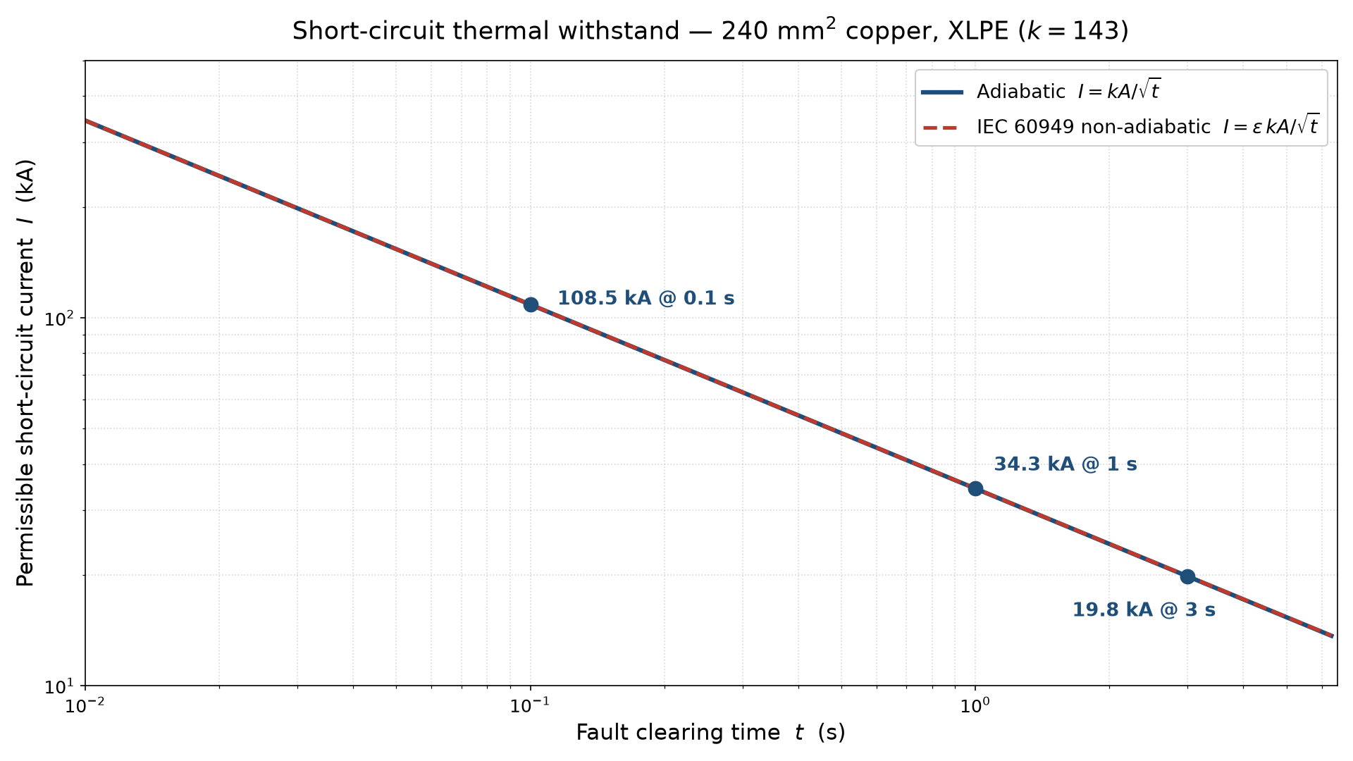
Figure 1. Permissible adiabatic short-circuit current for a 240 mm² copper XLPE conductor as a function of fault clearing time, plotted on logarithmic axes. Marked points show 108.5 kA at 0.1 s, 34.3 kA at 1 s, and 19.8 kA at 3 s. The dashed curve shows the reduced current from the IEC 60949 non-adiabatic correction at long durations.
On these logarithmic axes the adiabatic rule is a line of slope , and the tabulated points fall exactly on it. The figure makes the design trade-off immediately visible: moving to the left, toward faster clearing, buys withstand current cheaply, while allowing the fault to persist toward the right rapidly erodes the conductor's capability. The divergence of the non-adiabatic curve from the straight adiabatic line at long durations, discussed next, shows where the simple rule becomes conservative.
5. The Non-Adiabatic Correction of IEC 60949
5.1 Why the Adiabatic Rule Becomes Conservative
The adiabatic derivation assumes that none of the heat generated in the conductor escapes during the fault. For short faults this is an excellent approximation because heat conduction into the insulation is slow relative to the fault duration. As the fault duration lengthens, however, a measurable fraction of the heat does diffuse into the adjacent insulation and bedding, so the conductor stores less energy than the adiabatic balance predicts and its true temperature rise is lower. Consequently, for a given permitted final temperature, the conductor can actually carry a somewhat higher fault current than the adiabatic rule allows; the rule becomes conservative, and using it for long-duration faults leads to unnecessarily oversized conductors. IEC 60949 provides the standard method for recovering this margin without abandoning the analytical simplicity of the adiabatic result.
5.2 The IEC 60949 Correction Factor
IEC 60949 preserves the adiabatic current as a base value and multiplies it by a correction factor that is always greater than or equal to unity, so that the permissible non-adiabatic current is . The correction factor is expressed as:
where is the fault duration in seconds, is the conductor cross-sectional area in square millimetres, and and are constants that depend on the volumetric heat capacities and thermal properties of the conductor and of the surrounding insulation. Physically, the term in captures the heat conducted across the conductor-insulation boundary, whose influence grows as the diffusion depth increases relative to the conductor size, while the term in captures the deeper heat storage in the surrounding medium over longer faults. The constants and are tabulated in IEC 60949 for each conductor-insulation combination, and both correction terms vanish for large conductors or short times, correctly recovering the adiabatic limit .
5.3 Quantifying the Margin for the Worked Example
Applying the IEC 60949 correction to the 240 mm² copper XLPE cable at the 3 s clearing time (the case where the adiabatic rule is most conservative) recovers roughly eight percent of additional current. The adiabatic value of 19.8 kA rises to a non-adiabatic permissible current of about 21.4 kA once the heat conducted into the insulation over the three-second fault is credited. At the one-second and shorter clearing times the correction is negligible, confirming that the adiabatic rule is essentially exact for fast protection and that the non-adiabatic refinement is worth invoking only when fault durations extend to several seconds and conductor sizes are large. For most distribution designs, where protection clears faults well within a second, the adiabatic rule can be used directly with confidence that any error is both small and on the safe side.
6. Rating Constants Across Conductor and Insulation Types
The derivation of Section 3 shows that the rating constant is fully determined by the conductor metal, through the volumetric heat capacity and resistivity in , and by the insulation, through the initial and final temperatures in the logarithmic term. Evaluating the closed-form expression for the four common combinations of conductor metal and insulation reproduces the standard tabulated values, which are collected in Table 1.
| Conductor | Insulation | Initial θᵢ (°C) | Final θ_f (°C) | Rating constant k (A·s^{1/2}·mm^{-2}) |
|---|---|---|---|---|
| Copper | XLPE / EPR | 90 | 250 | 143 |
| Copper | PVC | 70 | 160 | 115 |
| Aluminium | XLPE / EPR | 90 | 250 | 94 |
| Aluminium | PVC | 70 | 160 | 76 |
Table 1. Adiabatic short-circuit rating constant k for common conductor and insulation combinations, derived from the material properties and permitted temperature excursions and matching the tabulated values of IEC 60364-4-43.
Two patterns in Table 1 follow directly from the physics of the derivation. First, copper conductors carry a higher than aluminium for the same insulation because copper's larger volumetric heat capacity relative to its resistivity gives it a greater value of the material constant ; copper stores more fault energy per unit temperature rise for each unit of resistive heating. Second, XLPE and EPR insulations yield a higher than PVC for the same metal because their 250 °C short-circuit limit permits a much wider temperature excursion than the 160 °C limit of PVC, and although the benefit enters only logarithmically it is still substantial. In design terms, a cable engineer converting a PVC-insulated design to XLPE gains short-circuit capability from two independent effects (the higher permitted temperature and, usually, the ability to run at a higher continuous rating), and Table 1 isolates the withstand component of that gain.
7. Practical Application and Coordination
The thermal withstand calculation is not a standalone check; it is one side of a matching condition against the protective device. The correct design procedure begins by determining the maximum prospective fault current at the cable from the system short-circuit study, then obtaining the total clearing time of the protective device at that current from its time-current characteristic, including any intentional time delay for coordination with downstream devices. The permissible withstand current is then computed from at that clearing time, and the design is acceptable only if the permissible current exceeds the prospective fault current. Equivalently, and more robustly for current-limiting devices, the check can be performed on an energy basis by confirming that the conductor's permissible exceeds the let-through published for the protective device; this energy comparison is preferred when the device limits the fault before the first current peak, because in that regime a nominal clearing time is meaningless.
The single most consequential judgement in the whole procedure is the choice of clearing time, because of the inverse-square-root sensitivity established in Section 4. Using the instantaneous element's clearing time when the fault is actually cleared by a delayed backup element is a common and dangerous error: it can overstate the permissible withstand current several-fold and leave the cable unprotected against a fault that persists into the backup zone. The conservative practice is to size the cable against the slowest credible clearing time in the coordination scheme that still applies to that fault location, and to verify the result against the fastest device only where current-limiting action can be relied upon. Where the calculated withstand at the governing clearing time is insufficient, the engineer's levers are, in order of typical preference, to speed up the protection, to increase the conductor cross-sectional area, or to upgrade the insulation system to raise the permitted short-circuit temperature, the first buying capability as , the second as , and the third only logarithmically.
8. Conclusion
The short-circuit thermal withstand of an insulated conductor is governed by an adiabatic energy balance that stores all fault energy in the conductor's own thermal mass, and integrating that balance with a temperature-dependent resistivity yields the rating constant and the familiar sizing rule directly from material properties rather than from tabulation alone. The worked 240 mm² copper XLPE example reproduces the standard and shows how strongly the permissible current depends on clearing time, ranging from 108.5 kA at 0.1 s to 19.8 kA at 3 s, which makes the protective clearing time the single most influential input to the check. For long-duration faults the IEC 60949 non-adiabatic correction recovers a modest but real margin (about eight percent at 3 s for this cable) while confirming that the adiabatic rule is essentially exact and appropriately conservative for the sub-second clearing times of modern protection.
For the practicing engineer the operative conclusions are three. Size the cable against the slowest credible clearing time that applies at the fault location, not the fastest device, unless current-limiting action can be relied upon; prefer the energy-basis comparison of conductor against device let-through when the protective device limits the fault before its first peak; and when the withstand is insufficient, remember that speeding up the protection buys capability as , enlarging the conductor as , and upgrading the insulation only logarithmically. Applied in that order, the method reconciles the cable and its protection into a single coherent design.
References
[1] IEC 60949, Calculation of Thermally Permissible Short-Circuit Currents, Taking into Account Non-Adiabatic Heating Effects, International Electrotechnical Commission, 2008.
[2] IEC 60364-4-43, Low-Voltage Electrical Installations, Part 4-43: Protection for Safety, Protection Against Overcurrent, International Electrotechnical Commission, 2017.
[3] ICEA P-32-382, Short-Circuit Characteristics of Insulated Cables, Insulated Cable Engineers Association, 2007.
[4] IEEE Standard 242-2001, Recommended Practice for Protection and Coordination of Industrial and Commercial Power Systems (IEEE Buff Book), IEEE, 2001.
[5] IEEE Standard 141-1993, Recommended Practice for Electric Power Distribution for Industrial Plants (IEEE Red Book), IEEE, 1993.